Retrofitting contour Height Data

Any questions regarding the practice version are asked and answered here.
Post Reply
Dean Penfold
Posts: 8
Joined: Fri Apr 29, 2016 10:04 pm

Retrofitting contour Height Data

Post by Dean Penfold »

Hello again,

Having gotten over my last issue, I have another question.

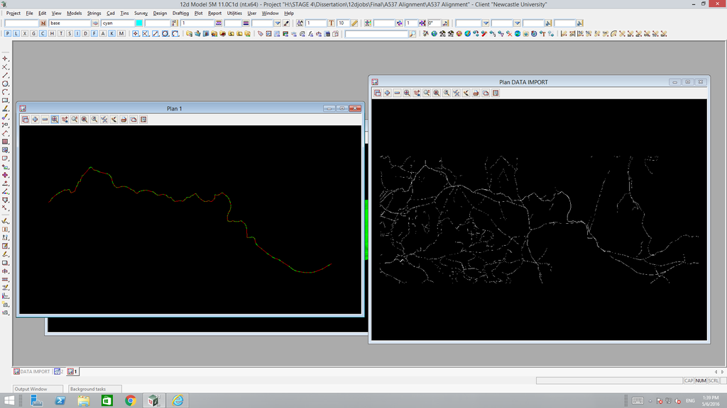
My dissertation requires that I recreate a road alignment so that I can analyse its geometry (specifically with regards to sight distance and how consistently road signage is used to forewarn a wide variety of potential hazards). For those based in the UK you may know the road; I have chosen the A537, once considered the UKs most dangerous road.

So, I have recreated the alignment by tracing over a topographic map of the area as pictured...
Image

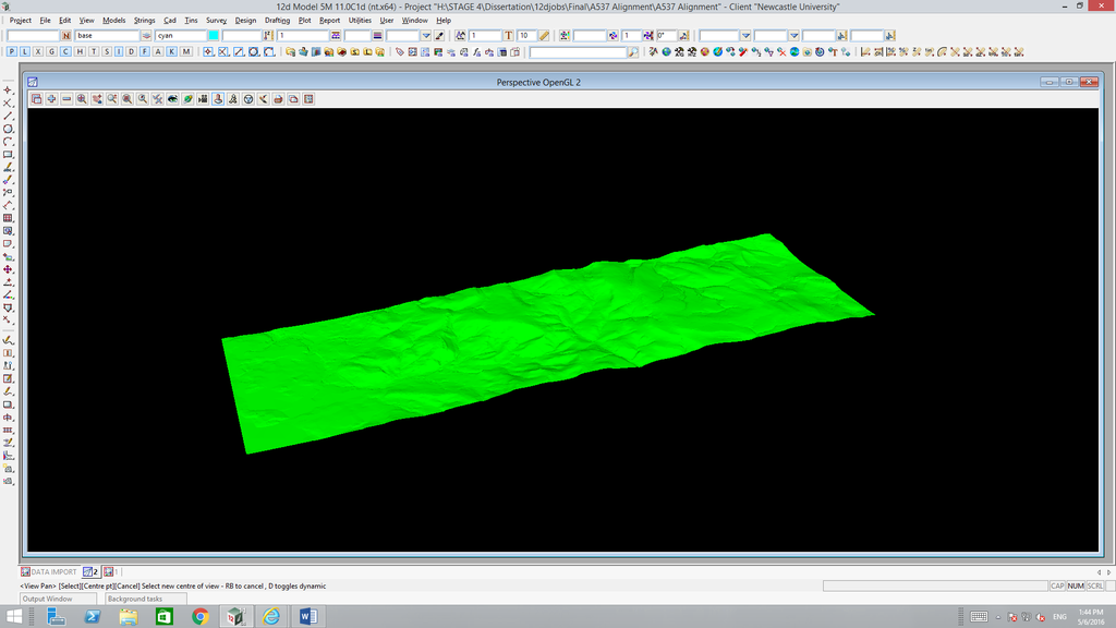
I also have the contour data which I have triangulated, meshed and shaded as pictured...
Image

I need to somehow lie the alignment over the terrain model I have created so that I can make use of the height data and make my alignment a 3D representation as opposed to 2D like it is currently. Is this possible or am I going to have to do some kind of interpolation and add height data to each point manually?

Hopefully this makes sense! Any help much appreciated!

Dean
Ed Wilson
Posts: 3002
Joined: Tue Oct 11, 2005 7:49 pm

Post by Ed Wilson »

Dean, sounds like an interesting project. An experienced road designer would knock this over and get a HD with about an hours work. may take you a bit longer;

is the terrain model accurate enough that you can make out the plan road centreline? If so, then you have probably got all you need. if the contours are too course (like say a 2 or 5m contour) then you may need to treat that terrain model like a survey on which you plough a new (/old) road.

Before going much further, ask your Council or Highways Agency office if they have records, preferably digital of the A537 Ask for a copy of the original design or a 'as constructed' record. You may find them skeptical, no doubt it will help if you explain your purpose is not to look for terrorist training grounds.

I would ask if they have the most recent design done in an electronic format like GENIO or DXF get that; you won lotto.

if you cant get any records of the real road, then you just need to follow the steps an invent a road from the terrain. The getting started manual for designers will have each and every step you need to follow - albeit on a different terrain to do that. Whether you get the real-design genio file or inevnt a design at the end of process you will have models of the road strings & surface tin and from that you can start looking at "SSD" visability and visability of signs or whatever..

NMost of what you need is well described in the The getting started manual for designers which you will find on this forum or www.12d.com
Owen Thornton
Posts: 5711
Joined: Tue Oct 04, 2005 12:50 pm
Location: Brisbane
Contact:

Post by Owen Thornton »

Tins created from contours are typically less accurate than those created from surveyed points and breaklines (from which contours are derived), but if that is the best information available, it will have to do.

There is an option in 12d to drape an alignment to a tin, so assuming the tin is good enough, that part is easy.

Is there enough detail in the contours of the road surface to see the extent of the road and the x-fall transitions. If not, any sight distances calculated will be rather questionable.

Sounds like the hard work in this project is establishing a good geometric model. Subsequent analysis of the sight distances should then be straightforward. (According to the internet, the A537 is 27 curvy kilometres long. I would hope that an experienced road designer would take a bit longer than an hour, to do a good job in this case.)
Michael Gunter
Posts: 1745
Joined: Fri Oct 21, 2005 8:47 am

Post by Michael Gunter »

Off topic but having had the pleasure of driving along the bit you are showing, (10 years ago) indeed it is one of the most dangerous roads I've ever been on courtesy of the numerous maniacs in trucks doing double the speed that would be unsafe in a car.
Dean Penfold
Posts: 8
Joined: Fri Apr 29, 2016 10:04 pm

Post by Dean Penfold »

Hi guys,

Sorry for the delay and thanks for the help with this.

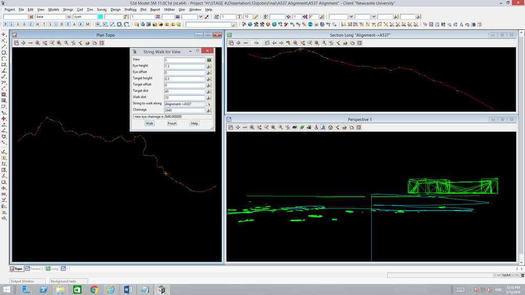
I've managed to recreate the alignment to a point that I can now drive the length of it and I'm happy that it matches as closely as I can afford to make it with the time I have available.

The last thing I need to do is to add in some basic site distance obstructions from buildings and trees however I'm struggling to do it. I've tried editing the topo map in AutoCAD and ArcMap to make the obstructing objects 3D before importing into 12d but it seem to do nothing once in 12d, they just remain 2D even in perspective view. I've tried importing a .dwg file that contain 3D building information but, although it shows up in AutoCAD, it doesn't show in 12d. I've also tried tracing over the building shapes and turning them into shapefiles in ArcMap to be imported into 12d but that doesn't work. Finally, I've tried using the CAD tools in 12d to draw them straight into the model but again, I can't figure it out...

Any ideas how I can do this easily without having to create templates? They will just be basic 3D blocks, nothing fancy.

Thanks,

Dean
Glenn Coppard
Posts: 233
Joined: Thu Jul 24, 2008 7:44 am

Post by Glenn Coppard »

Have a look at using the 'Tins->User->Create buildings for TINs' option.

Usually you will have building footprints (from GIS) to use as the base data.

Not sure if it will work on circles (eg. trees) unless the super strings have a small 'interval' applied to them. (Ed has explained how HERE)

'Once you have your 'floor' and 'floor and roof' model you can then triangulate them, then null it outside the 'model of polygons' (being the 'floor' model) and you can then use this as an obstruction tin or create a super tin with the existing.


edit: Also, if they are created as 3d solids in autocad, they should import as Trimeshes.
Ed Wilson
Posts: 3002
Joined: Tue Oct 11, 2005 7:49 pm

Post by Ed Wilson »

Errr - I thought the 3d objects you can insert from the Viz mesh library (cars, trees, houses etc) would work in advanced sight distance
Dean Penfold
Posts: 8
Joined: Fri Apr 29, 2016 10:04 pm

Post by Dean Penfold »

I've tried what you suggested Glen and at first I thought it had worked, however doing so seems to have made no difference to the 'Advanced Sight Distance' output suggesting it is not recognising them as obstructions...

I did what you said and used the building footprints from my topo map to create the 'floor' and 'floor and roof' models. I then triangulated them which seemed to work as below

Image

I then selected the relevant tin for the obstructions tab of the 'Advanced Sight Distance' tool. Problem is the sight distances are the same as the output I got when ran without the building obstructions.

I tried combining the terrain and building obstructions tins into a super tin so that I could bypass the need to include the build obstructions tin separately as obstructions for the 'Advanced Sight Distance' tool but for whatever reason I can't seem to figure out how to do it. I keep getting an error message when I try to input a tin for the 'super tin' option.

Any ideas?

Ed, I'm not sure exact6ly what the Viz mesh library is?

Thanks,

Dean
Dean Penfold
Posts: 8
Joined: Fri Apr 29, 2016 10:04 pm

Post by Dean Penfold »

Actually, scrub that last post, I seem to have figured it out!

That worked a treat Glenn, thanks a lot for the help.

Dean
paul hardwick
Posts: 1639
Joined: Thu Dec 06, 2007 9:27 am

Post by paul hardwick »

The Vis Library is a library of 3D objects that you can place into your data.
And as Ed mentioned they should work in SD calcs.
You can also create your own or import from other 3D modelling packages.
Post Reply